Hunting a 2.5 mA Phantom Leak in Deep Sleep
How we took the Cyber Fidget's standby current from 2.51 mA down to 265 µA, a 9.5× improvement from software-only change, and what it taught us about mixed-power-domain I2C buses, ESD protection diodes, and the importance of trusting the math.
TL;DR
| Stage | Sleep current | Battery life on a 400 mAh cell |
|---|---|---|
| Original firmware | 2.51 mA | 6.6 days |
| After OLED ESD-diode fix | 292 µA | 57 days |
| After fuel-gauge + accelerometer teardown | 265 µA | 63 days |
The original "deep sleep" was burning a battery's worth of energy in a week. Most of that turned out to be a phantom current path through the OLED display's input ESD protection diodes, the kind of leak you only notice when you instrument the bench with enough precision, and the kind of mechanism that doesn't show up in any block diagram.
Early prototypes used ubiquitious USB power meters and the results were encouraging because the meters read as low as they would go (0.001A and energy reports for about $15). But it turns that that simply wasn't precise enough and was just within the noise.

As the developer, it wasn't really a problem since it's constantly plugged in getting reflashed and charging, but user feedback drove the purchase of a Nordic nRF-PPK2 that can read down to 0.0000001A (100 nA!) reliabily. This means we can use our old V (voltage) = I (current) x R (resistance) equation across components using microamps (µA) of current to see what's happening. This enables true board validation of energy usage across the physical electrical design as well as the firmware's behavior running on that hardware.
This post walks through the bench setup, hypothesises that did and did not work, the math that finally nailed the culprit, and the firmware fix in HAL::enterDeepSleep() that should get the Cyber Fidget from a week of standby time to two months. If you're chasing power on an ESP32 design with a multi-rail power architecture, the diagnostic pattern here will hopefully save you some time.
Why we cared
The Cyber Fidget runs off a 400 mAh single-cell LiPo. The active-mode current pulls 45–80 mA depending on what's running, which gets you about 5–8 hours of continuous use. This was expected for an ESP32 with a display and audio, and honestly fine.
What's not fine is the standby performance. We expected that putting the device into "deep sleep", say intentionally via the Power Manager, would drop the device to a few microamps. We hadn't actually measured it carefully before. So we plumbed up a Nordic Power Profiler Kit II (PPK2) and started measuring.
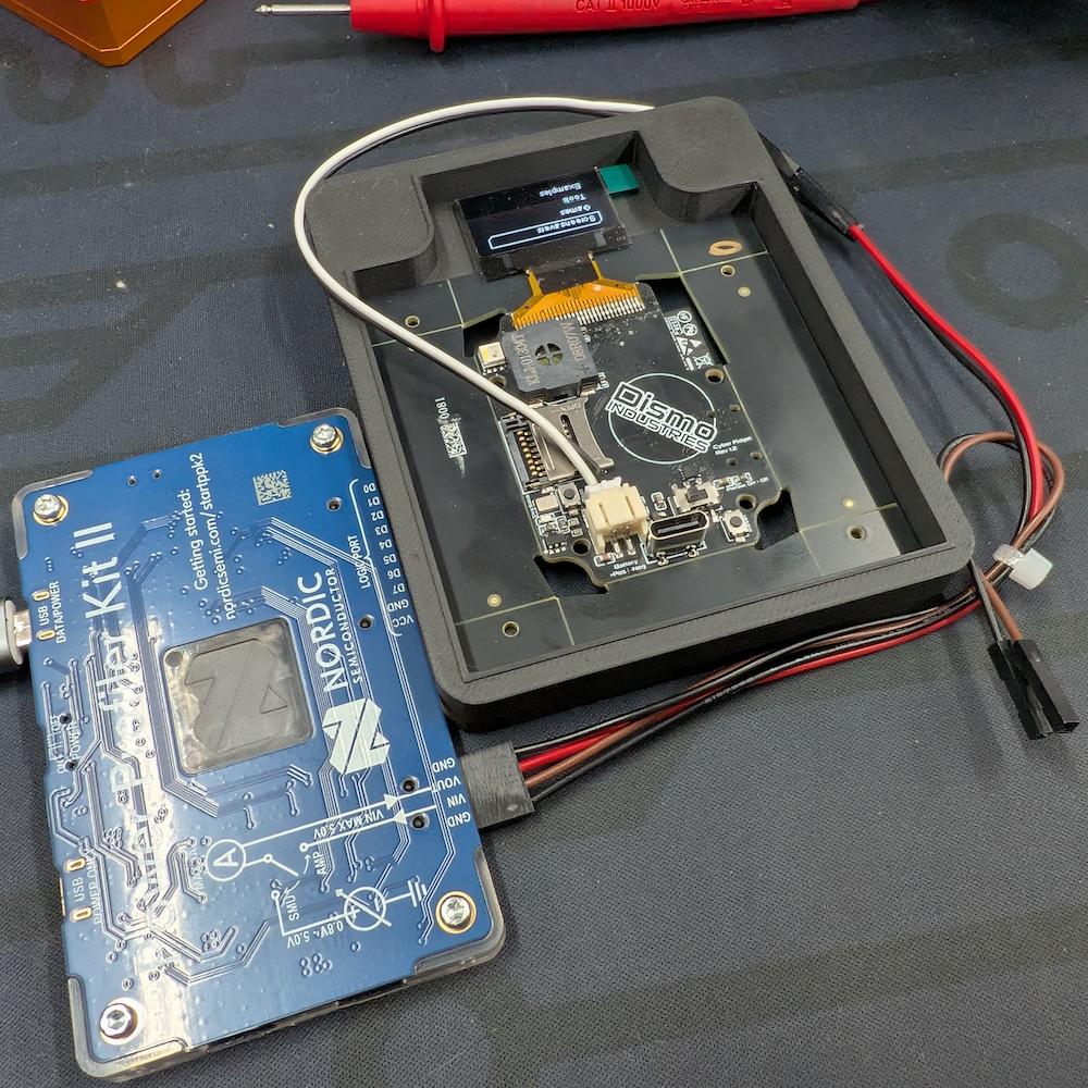
The bench
The PPK2 has two relevant modes for this kind of work:
- Source meter mode - the PPK2 acts as a tunable voltage source (0.8–5 V, up to 1 A) and measures its own output current with high resolution down to nA-scale. You wire it in place of the battery, and it both powers the device and tells you exactly what current is flowing.
- Ampere meter mode - a real cell powers the device, the PPK2 sits in series and just measures.
For deep-sleep characterization, source-meter mode was used: you can hold VBAT at a fixed, tunable voltage indefinitely, you don't have to worry about battery state of charge changing under you, and the µA-range resolution is perfect for sub-mA leak hunting.
The wiring is straightforward - two wires from the PPK2's VOUT and GND to the JST battery connector pins (polarity confirmed against the PCB silkscreen with a multimeter beforehand - always do this first, the cost of getting it wrong is a smoked board).
A few practical notes on this kind of bench:
- USB bypassing battery port measurement When the USB-C is plugged into the Cyber Fidget, it actually switches the power paths via Q1. This means that without a specially modified Cyber Fidget mainboard, the battery JST port will read 0 current until USB power is disconnected.
- USB serial coupling matters. When the Cyber Fidget's USB-C is plugged into the same host computer as the PPK2, you have two ground paths and the µA range gets noisy. For sub-mA work, you either disconnect USB during the measurement window or use a galvanic USB isolator. We used the disconnect-and-measure workflow here: set up the test state via serial, unplug USB, capture, plug back in.
- The PPK2's source mode has limited transient response. Cold-boot inrush on the ESP32 is ~150 mA peaks; the PPK2 handles it but you may want a 1000 µF bulk cap across the JST for cleaner edges if you're characterizing fast transients.
- Set the current limit appropriately. In general a current limit should be set on power supplies. I didn't see an obvious way to set it in the Power Profiler v4.3.1 app.
First measurement: Whoops
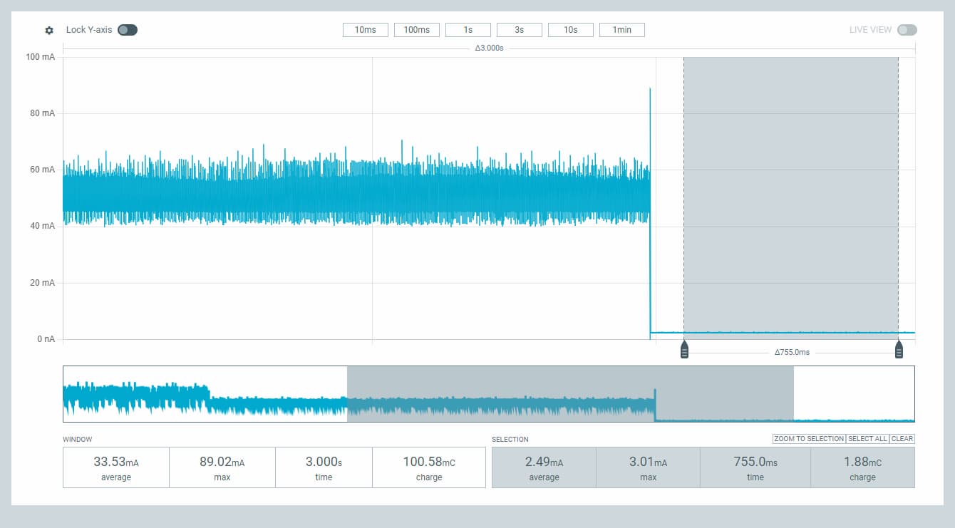
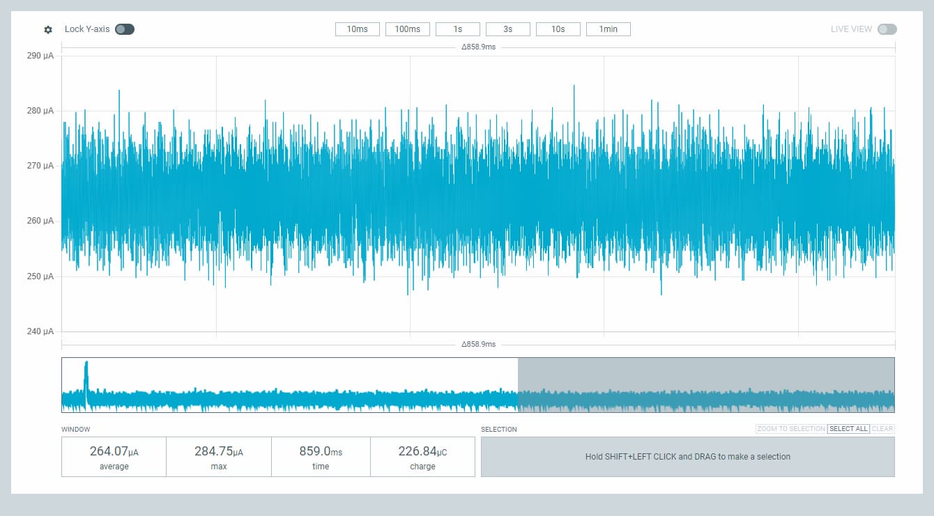
With the PPK2 holding VBAT at 3.7 V and no USB connected, we triggered the Power Manager shutdown sequence and watched the trace. The numbers:
| State | Current | Notes |
|---|---|---|
| Active (app manager idle) | 64 mA avg | Reasonable for ESP32 + OLED |
| App-manager active cycling | 45–80 mA | Fine |
| Wake/boot transient | ~145 mA peak | Within budget |
| "Deep sleep" (firmware-claimed) | 2.51 mA avg, 2.83 mA max | Way over the original 375 µA design target |
That's not deep sleep. ESP32 real deep sleep should be 10–150 µA depending on which RTC peripherals you keep alive for wake sources. 2.5 mA is the textbook number for light sleep with peripherals running. So either the firmware wasn't actually entering deep sleep, or something on the board was leaking the rest.
The visual step-down on the PPK2 trace was clean, the firmware was hitting esp_deep_sleep_start(), and the screen shut off as expected. So the call was happening. The question was where 2.5 mA was disappearing to.
The suspect list
Before getting clever, we wrote down what could plausibly be drawing this much current with no USB connected:
- The CP2102N USB-serial chip - if powered from the system rail rather than from VBUS, it could draw ~1–2 mA waiting for a USB connection that never comes
- The MCP73831 charge LED - if the STAT pin is in the wrong state, the LED leaks ~650 µA
- WiFi/BT not properly torn down before sleep - the radio can stay partially active, drawing a few mA
- Various pull-up resistors holding the wrong line low through the wrong path
- ESP32 itself in a sub-optimal sleep mode - if
esp_deep_sleep_start()somehow fell through to light sleep - The OLED display - if its power rail wasn't actually disabled
- The fuel gauge / accelerometer in normal-mode rather than low-power mode
We ruled them out one at a time.
Ruling things out
Suspect 1: CP2102N USB-serial chip
The CP2102N has three viable power configurations per the SiLabs datasheet. We needed to figure out which one was on our board. Looking at the schematic showed VBUS tied to the chip's VBUS pin (USB-detect input) and its VREGIN pin (LDO input) - that's the textbook bus-powered configuration. In that mode, when USB is unplugged, VREGIN drops to 0 V, the internal LDO dies, and the chip is fully off.
Confirmed with a multimeter on the chip's VDD pin (the LDO output) with USB unplugged: <20 mV. Chip is dead. Innocent.
Suspect 2: Charge LED and MCP73831
Visual check first - with USB unplugged and the PPK2 sourcing the JST, was the charge LED illuminated? No. The MCP73831 datasheet confirms it: when VDD < (VBAT − 50 mV), the chip enters UVLO shutdown with ≤5 µA reverse leakage. STAT goes high-impedance, no current through the LED. Innocent.
Suspect 3: WiFi/BT not stopped before sleep
The Cyber Fidget firmware uses WiFi (in the Web Portal app) and Bluetooth (in the Music Player app). Neither is gated explicitly stopped in the Power Manager's shutdown path before esp_deep_sleep_start(). ESP-IDF requires esp_wifi_stop() and esp_bt_controller_disable() to fully power down those radios for sleep - without them, you can leave the radio circuit active.
Test: power-cycle the device, navigate straight to the Power Manager (without ever entering Web Portal or Music Player), trigger shutdown. If WiFi/BT residual state was the leak, the cold-boot path should be much lower.
Result: still 2.51 mA. Not WiFi/BT. (Worth a future follow-up to add the teardown calls anyway as defense-in-depth, but not the leak we were chasing.)
Suspect 4: ESP32 I2C peripheral leaving the bus held low
This was the first hypothesis with real potential. The Cyber Fidget has a shared I2C bus with the OLED, accelerometer, fuel gauge, and (intended-but-depopulated) hall sensors on it. Pull-ups are 2.2 kΩ to the always-on 3.3 V rail. If the ESP32's I2C peripheral leaves SDA or SCL pulled low at sleep entry, current flows through the pull-up: 3.3 V / 2.2 kΩ = 1.5 mA per line. Both lines stuck = 3 mA. Right in the ballpark.
The fix should have been simple: add Wire.end() plus pinMode(SDA, INPUT) and pinMode(SCL, INPUT) before esp_deep_sleep_start(). This deinitializes the I2C peripheral and explicitly sets the pins as high-impedance inputs, letting the external pull-ups bring them HIGH. We applied the fix, flashed, and re-measured.
Still 2.51 mA.
The ESP32 was supposed to be releasing the bus cleanly to avoid erroneous power consumptuion, but it wasn't. Time to get the multimeter and figure out what was actually happening on those lines.
The smoking gun: 0.85 V
We probed MCU_SCL and MCU_SDA at the bus level via the 2.2 kΩ pull-up resistors during the "deep sleep" plateau:
- MCU_SCL: 835 mV
- MCU_SDA: 875 mV
This is one of those moments that's worth dwelling on, because the specific voltage tells you the mechanism.
If the ESP32 were fully driving the lines low (Rdson is ~30 Ω for an open-drain output), the lines would sit at:
3.3 V × 30 Ω / (2200 Ω + 30 Ω) ≈ 45 mV
If the I2C teardown were working and the ESP32 had cleanly released the pads, the lines would sit at the pull-up rail voltage: ~3.3 V.
It was neither. They were sitting at ~0.85 V. That's not "driven low" and it's not "released." It's an equilibrium voltage set by something else pulling the lines down through some non-trivial impedance. The math:
V_line = 3.3 V × R_pulldown / (2.2 kΩ + R_pulldown)
Solving for R_pulldown given V_line = 0.85 V gives ~760 Ω of equivalent resistance to ground per line. That's a lot. ESP32 output FETs aren't 760 Ω. ESP32 internal pull-downs aren't 760 Ω (they're ~45 kΩ if even available on the pins, which would put the line near 3.15 V).
Whatever was pulling the line down wasn't the ESP32. So we went looking at what else was on the bus.
What's actually happening: ESD diode forward-bias
Every CMOS chip's input pins have ESD (electrostatic discharge) protection diodes. There's one from each pin to the chip's VDD, and one from each pin to GND. They're there to clamp ESD strikes - when a pin sees a voltage spike above VDD or below GND, the diode conducts and shunts the energy through the supply network.
These diodes are normally reverse-biased and invisible. But what if VDD is below the pin voltage?
The Cyber Fidget has a switched OLED power rail (3.3V_OLED) controlled by a GPIO. When the firmware enters deep sleep, the GPIO goes high-impedance, an external pull-down on the regulator's enable pin wins, and the rail collapses to 0 V. We confirmed this with a multimeter - 3.3V_OLED reads ~100 mV during sleep, basically off (the small residual is exactly the leak we're about to explain).
Now the SSD1306 OLED controller is in a weird state. Its VDD pin is at ~0 V. But its SCL and SDA pins are still wired to the shared I2C bus, which is at ~3.3 V (the always-on rail powering R50 and R51). With the input pin above VDD, the ESD diode from SCL to VDD becomes forward-biased:
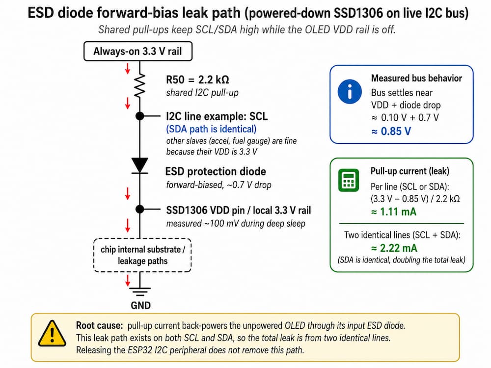
The current flows: pull-up rail → R50 → SCL bus → SSD1306 ESD diode → SSD1306 VDD pin → through the chip's internal substrate to GND. The bus settles at one diode-drop above the powered-down VDD: roughly 0.7 V + the residual VDD voltage = 0.85 V, exactly what we measured.
Per-line current:
(3.3 V − 0.85 V) / 2.2 kΩ = 1.11 mA
Two lines (SCL + SDA): 2.22 mA.
Add ~150 µA for the rest of the system (RTC peripherals kept alive for the wake source, the always-on AP2112K LDO's quiescent current, the fuel gauge in active mode, the accelerometer in normal mode) and you get ~2.4 mA - within measurement tolerance of the 2.51 mA we observed.
That math fitting that cleanly and looking like the smoking gun. The ESP32 was innocent. The bus master had nothing to do with the leak. The leak path was between the pull-up resistor and the powered-down slave, with the ESP32 watching from the sidelines. Releasing the I2C peripheral was correct hygiene but couldn't possibly fix the root cause.
Why specifically the OLED (and not some other chip on the bus)?
Worth pausing on this question because the answer is reassuring. The Cyber Fidget shares its I2C bus across several devices:
| Device | Power rail | State during deep sleep |
|---|---|---|
| LIS2DH12 accelerometer | 3.3V_ACCL = 3.3V (always on) | Powered. VDD = 3.3 V. |
| MAX17048 fuel gauge | VBAT (always on) | Powered. VDD = 3.7 V. |
| SSD1306 OLED display | 3.3V_OLED (switched, GPIO-controlled) | Rail collapsed to ~100 mV during sleep. |
| Rotary / linear hall sensors | (depopulated on production boards) | N/A |
Every one of these chips has the same kind of input ESD protection diodes. But ESD diodes only forward-bias when the input pin voltage exceeds VDD. The accelerometer and fuel gauge both have their VDD pinned at 3.3 V or higher — same as (or higher than) the I2C lines — so their ESD diodes stay reverse-biased and don't conduct. Only the SSD1306, whose VDD collapses while its input pins are still being held at 3.3 V by the always-on pull-ups, is in the failure regime.
The math closes the loop. There's only one chip on the bus whose VDD goes below the bus voltage, and that single chip's ESD diodes account for exactly the leak we measured.
The OLED datasheet actually hinted at this
After we worked it out the hard way, we went back to the SSD1306 module datasheet (Newvision N096-2864KSWEG01-H30, the OLED panel on the Cyber Fidget) and found this gem in the I2C reference-design section:
特别提醒(Special Tips):主板设计务必加电子开关, 否则, 可能引起漏电流现象 (When design main board, Please add Electronic Switch circuit, otherwise, will be caused leak current)
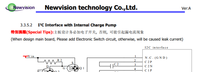
The "电子开关" (electronic switch) the warning refers to is the Q1 (FDN338P) + Q2 (FDN335N) high-side FET circuit shown in their reference designs - a power-gating switch on the OLED's VBAT/VDDB power pins.
The Cyber Fidget design did include a switch in that spirit: REG_OLED1 (an AP2112K LDO) gates the OLED's VDD via a GPIO-controlled enable pin. So at the rail level, we followed the manufacturer's recommendation.
But the warning is incomplete in a specific way. It tells you to gate the OLED's power rail, but it doesn't explicitly call out the corollary: any shared bus signals, like I2C SCL and SDA, also have to die with the OLED's power, otherwise current still flows through the input ESD diodes regardless of how nicely you've gated VDD. Their reference designs may or may not implicitly handle this (they don't show any detailed internal schematics), but the warning text itself only talks about VBAT/VDDB.
It's a useful generalization for any embedded design: manufacturer warnings about subtle electrical behaviors are often incomplete. They flag the concern but leave the deeper implications as an exercise for the reader. Worth treating them as a hint to think harder rather than a complete specification of the failure mode.
Final confirmation (if you want to be 100% sure)
The elimination argument plus the quantitative fit is strong evidence, but if you have a board with the OLED physically removed - say, a unit with a damaged flex cable and the display was depopulated without concern - you can run the exact same deep-sleep measurement on it. Predicted result: the 2.2 mA leak completely vanishes, leaving only the structural ~50–100 µA floor that doesn't depend on any I2C slave.
We didn't run this test ourselves because the math seems like reasonable confirmation. But for anyone reproducing this kind of debug on a different design, the "remove the suspect chip and re-measure" test is the gold standard for confirming a leak path. There's no replacement for empirical isolation.
The fix
There are a few ways to break this leak path. The clean hardware answer is to either move the pull-ups to the switched rail (so they die when the OLED rail dies) or add an analog bus switch between the bus and the SSD1306 (so the chip is electrically isolated when its rail is off). Both require a board revision, which we didn't want to wait for.
The firmware answer that works on existing hardware is: keep the OLED rail powered through deep sleep. If the SSD1306's VDD stays at 3.3 V (matching the pull-up rail), the ESD diodes stay reverse-biased and the leak path closes. The cost is the AP2112K LDO's quiescent current (~55 µA) plus the SSD1306 itself in software display-off mode (~10 µA), for about ~65 µA total. Way better than 2.2 mA.
The implementation in HAL::enterDeepSleep():
void enterDeepSleep()
{
    // Put the SSD1306 into low-power display-off mode (command 0xAE).
    s_realDisplay.displayOff();

    // Release the I2C master cleanly. (Necessary hygiene, but
    // alone does NOT close the ESD-diode leak path - the rail
    // hold below is what does.)
    Wire.end();
    pinMode(SDA, INPUT);
    pinMode(SCL, INPUT);

    // Keep the OLED rail powered through deep sleep so the
    // SSD1306's VDD stays equal to the always-on 3.3V pull-up
    // rail and its ESD diodes don't forward-bias from the I2C
    // lines.
    digitalWrite(POWER_PIN_OLED, HIGH);
    gpio_hold_en((gpio_num_t)POWER_PIN_OLED);
    gpio_deep_sleep_hold_en();

    esp_deep_sleep_start();
}
Two ESP-IDF functions worth highlighting here:
gpio_hold_en(pin)latches the GPIO's current output state through deep sleep. Without this call, the GPIO would go high-impedance whenesp_deep_sleep_start()runs, and the AP2112K's pull-down would win - the rail would die just like before.gpio_deep_sleep_hold_en()extends the hold across the deep-sleep transition itself.
There's a subtle gotcha with these calls that bit us briefly: the hold persists across the wake boundary. After the device wakes, any later digitalWrite() to a held pin silently fails until you call gpio_hold_dis() to release it. We added a release at the top of initHardware() to make sure the next boot's GPIO setup actually takes effect:
void initHardware()
{
    // Release any GPIO holds latched across the previous deep sleep
    // before any pinMode/digitalWrite tries to drive a held pin.
    gpio_hold_dis((gpio_num_t)POWER_PIN_OLED);
    gpio_deep_sleep_hold_dis();

    // ... normal pinMode / digitalWrite setup ...
}
Validation
Re-flashed, re-measured.
- MCU_SCL: 3.289 V (was 0.835 V)
- MCU_SDA: 3.289 V (was 0.875 V)
- 3.3V_OLED rail: 3.316 V (was 100 mV - confirming the rail hold worked)
- PPK2 average current in deep sleep: 292 µA (was 2.51 mA)
8.6× improvement in one fix. The math from the diagnostic step predicted ~2.2 mA of savings; we got 2.22 mA. The model held.
Long-tail wins
With the main leak closed, the remaining 292 µA is dominated by smaller contributors. Two of them are easy software fixes worth doing while the bench is set up:
MAX17048 fuel gauge in forced hibernate. The default behavior is "auto-hibernate after 6 minutes of low cell-voltage change rate." If you don't want to wait 6 minutes - or if you want to deterministically be in hibernate at sleep entry - write 0xFFFF to the HIBRT register. Drops gauge supply current from ~23 µA active to ~4 µA. The SparkFun library exposes this as lipo.enableHibernate(). Hibernate auto-clears on the next sufficiently-large VCELL change (e.g., when a charger is plugged in), so no disableHibernate() is needed at wake.
LIS2DH12 accelerometer in power-down mode. The default mode draws ~11 µA. Setting accel.setDataRate(LIS2DH12_POWER_DOWN) drops it to ~0.5 µA. The accelerometer is reconfigured by s_accel.begin() on next boot, which restores the default rate. Potentially affects future wake-on-tap type behaviors, but currently untested and unused making it a fair trade for now.
Both calls go right next to the displayOff() call, before the I2C teardown:
s_batteryManager.prepareForDeepSleep();      // MAX17048 → hibernate
s_accel.setDataRate(LIS2DH12_POWER_DOWN);    // LIS2DH12 → power-down
s_realDisplay.displayOff();                  // SSD1306 → display-off standby
After flashing: 265 µA in deep sleep. That's another ~27 µA savings, matching the predicted ~30 µA almost exactly.
The numbers
Pulling it all together:
| Stage | Current | Battery life on a 400 mAh cell |
|---|---|---|
| Original firmware | 2.51 mA | 6.6 days |
| After OLED ESD-diode fix | 292 µA | 57 days |
| After fuel-gauge + accelerometer teardown | 265 µA | 63 days |
For context: ESP32+display devices in the wild typically come in at 100–500 µA in deep sleep with careful firmware, or 1000–3000 µA with naive firmware. We started at the bottom of "naive" because of the OLED ESD bug. After the fix we're solidly in "careful" territory.
What's left at 265 µA
The remaining current is now structural. Here's the breakdown:
| Source | Estimated draw |
|---|---|
RTC_PERIPH power domain (kept alive for EXT0 wake on the button) |
~150 µA |
| Always-on AP2112K (REG_MAIN1) quiescent current | ~55 µA |
| AP2112K (REG_OLED1) quiescent current - held on for the ESD-diode mitigation | ~55 µA |
| SSD1306 in display-off standby | ~10 µA |
| MAX17048 in forced hibernate | ~4 µA |
| LIS2DH12 in power-down | ~0.5 µA |
| Misc pad leakage, RTC slow oscillator, etc. | ~5–10 µA |
| Sum | ~280 µA |
Within ~5 % of measured. None of these are bugs - they're the actual expected energy of the design.
To go meaningfully lower without changing the board, we'd need to remove the EXT0 wake source (which kills the button-wake feature, not acceptable) or stop holding the OLED rail on (which re-opens the ESD-diode leak). Both blocked.
To go lower with board changes, two levers exist:
- Active-high buttons instead of active-low. ESP32's EXT1 wake source supports "any pin high" as a wake condition without needing the
RTC_PERIPHpower domain alive. If buttons are pull-down (active-high), EXT1 works and saves ~140 µA. Today our buttons are active-low pull-up, so we're stuck with EXT0 which keepsRTC_PERIPHpowered. - I2C bus isolation for the SSD1306. Either move R50/R51 to the switched OLED rail, or add an analog bus switch (FSA2257-class part, ~$0.50 in BOM) between the shared bus and the SSD1306's pins, gated by the OLED rail. Either eliminates the ESD-diode leak path without needing to keep the OLED rail powered, saving the ~55 µA AP2112K Iq we currently pay.
Combined, those two changes get us toward ~80 µA, which translates to roughly 6 months of standby on a full 400 mAh cell. Both are captured for investigating for the next mainboard rev.
A more ambitious path is migrating the MCU to ESP32-S3, which has a native USB peripheral (eliminating the CP2102N entirely) and more flexible wake sources. That's a full board redesign, not a small spin, but it'd put the floor closer to ~50 µA - close to what dedicated low-power MCU families like nRF52 achieve. But potentially trading learned robustness and software compatibility without proper due dilligence.
Lessons that generalize
A handful of things from this investigation are worth carrying forward to any embedded design:
1. Mixed power-domain I2C buses leak through ESD diodes. Any time a shared I2C bus has its pull-ups on a different rail than one of the slaves, and that slave's rail can be cut independently, you have a potential leak path. The pull-ups source current through the bus into the powered-down slave's input ESD diodes. Either co-locate pull-ups with the most likely-to-be-powered-down slave, or insert isolation between the bus and that slave.
2. esp_deep_sleep_start() doesn't tear down peripherals for you. WiFi, Bluetooth, I2C, SPI, custom power rails - all of these need explicit teardown calls before esp_deep_sleep_start(). The kernel call is just "halt the CPU and configure wake sources." The rest is your responsibility.
3. The "between 0V and Vdd" reading is diagnostic gold. When a digital line is supposed to be either fully driven or fully released, an intermediate voltage is the signature of an unintended path. Always do the math: V × R between the rail and the line, divided by the pull-up resistance, gives you the leak current. If that current matches the headline measurement, you've found your culprit.
4. Trust the math. When the predicted leak (from the voltage-divider model) matches the measured leak (from the PPK2) within a few percent, you've identified the mechanism with high confidence. When they don't match, your model is incomplete and you need to keep looking. We bisected suspects for hours before getting to the multimeter; the math nailed it in 30 seconds once we had the reading.
5. Hold-state lifecycle matters. ESP32's gpio_hold_en / gpio_deep_sleep_hold_en is a great tool for keeping rails enabled through sleep, but the hold persists across wake. Always pair every gpio_hold_en() with a gpio_hold_dis() at the next boot, in the same pattern as malloc/free or open/close.
Bench notes for anyone trying this at home
- The PPK2 in source-meter mode is the right instrument for this. ~$110 from Adafruit/Mouser/DigiKey. The cheaper alternative (a benchtop supply + DMM or basic USB power meter) won't give you the µA resolution or the time-correlated current trace that makes leak hunting tractable.
- A multimeter probe set with very fine tips makes a huge difference for probing surface-mount ICs and dense pad geometry without bridging. In the case of the Cyber Fidget which intentionally has bigger SMD components or components with exposed legs, standard Fluke probes worked just fine.
- For mixed-domain leak hunting like this one, you need both instruments simultaneously. The PPK2 tells you the aggregate current; the multimeter tells you where on the board the current is sinking. Without the multimeter probe, you'll never localize.
- Single-axis lab benches with a spare USB hub on a power switch are worth setting up. Plugging and unplugging USB during a measurement window is fine for a one-off, but if you're iterating you want to flip a switch instead.
What's next
This work covers firmware-side optimizations on the existing hardware. The board-rev mitigations (active-high buttons, I2C bus isolation) are the next big lever, and an ESP32-S3 migration is a longer-term consideration that would unlock the floor below ~80 µA. Those are tracked separately in our planning system.
If you're doing similar work and run into a head-scratching µA-scale leak, drop us a note - we'd love to compare diagnostics.