3D model file format (.cfmesh.json)
By the end of this page you can read a .cfmesh.json file field by field, write one by hand, and know which mistakes the Studio refuses.
A .cfmesh.json file holds one wireframe model: a list of points and a list of lines that join them. The Studio's 3D tab saves models in this file, and models move in and out of a project as these files (see Import & export). You do not need to know the format to draw or use a model. This page is for reading a model file, writing one by hand, or making a tool that produces them.
The shape of a file
A file is a JSON object with four fields. All four are required. No other top-level field is allowed.
{
  "schemaVersion": 1,
  "meta": { "name": "pyramid", "kind": "mesh", "author": "", "license": "", "symmetry": "x" },
  "vertices": [[-9, -6, -9], [9, -6, -9], [9, -6, 9], [-9, -6, 9], [0, 10, 0]],
  "edges": [[0, 1], [1, 2], [2, 3], [3, 0], [0, 4], [1, 4], [2, 4], [3, 4]]
}
| Field | Type | What it is |
|---|---|---|
schemaVersion |
whole number | Which version of the format the file uses. The only version is 1. A missing or different value is refused. |
meta |
object | The model's name and notes about it. See The meta object. |
vertices |
list of [x, y, z] |
The model's points, called nodes in the Studio. See Vertices. |
edges |
list of [a, b] |
The model's lines, called struts in the Studio. See Edges. |
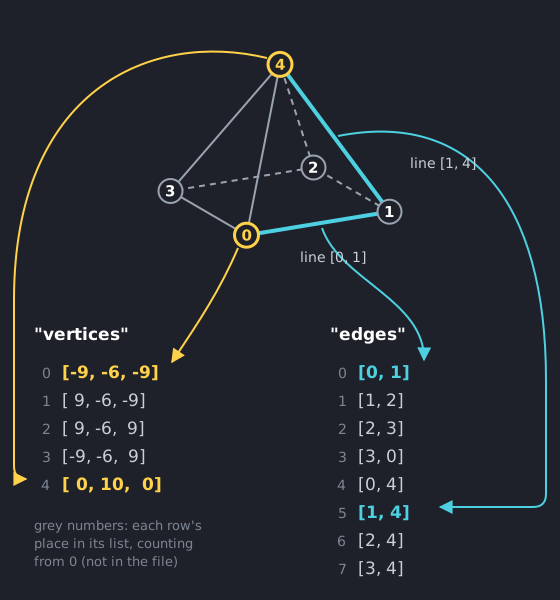
Each row of vertices is one point, and each row of edges joins two points by their place in the vertices list, counting from 0. In the picture, point 0 and point 4 are the first and last rows of vertices, and the line from point 0 to point 1 is the first row of edges:
The meta object
meta must be an object. Only name and kind are checked. The object is open: other keys are allowed.
| Field | Type | Rule |
|---|---|---|
name |
text | Required, and not empty. It becomes the model's name in your app's code (see How a file becomes code). |
kind |
text | Required, and must be exactly "mesh". |
author |
text | Who made the model. The Studio starts it empty. Not checked. |
license |
text | The license the model is shared under, such as GPL-3.0-or-later. The Studio starts it empty. Not checked. |
symmetry |
text | A note about the model's shape. The Studio's starter models use "x" for a model that is the same on the left and the right, and "none" for one that is not. Nothing checks it, and it does not change how the model is built or drawn. |
Vertices
vertices is a list of points. Each point is a list of exactly three whole numbers, [x, y, z].
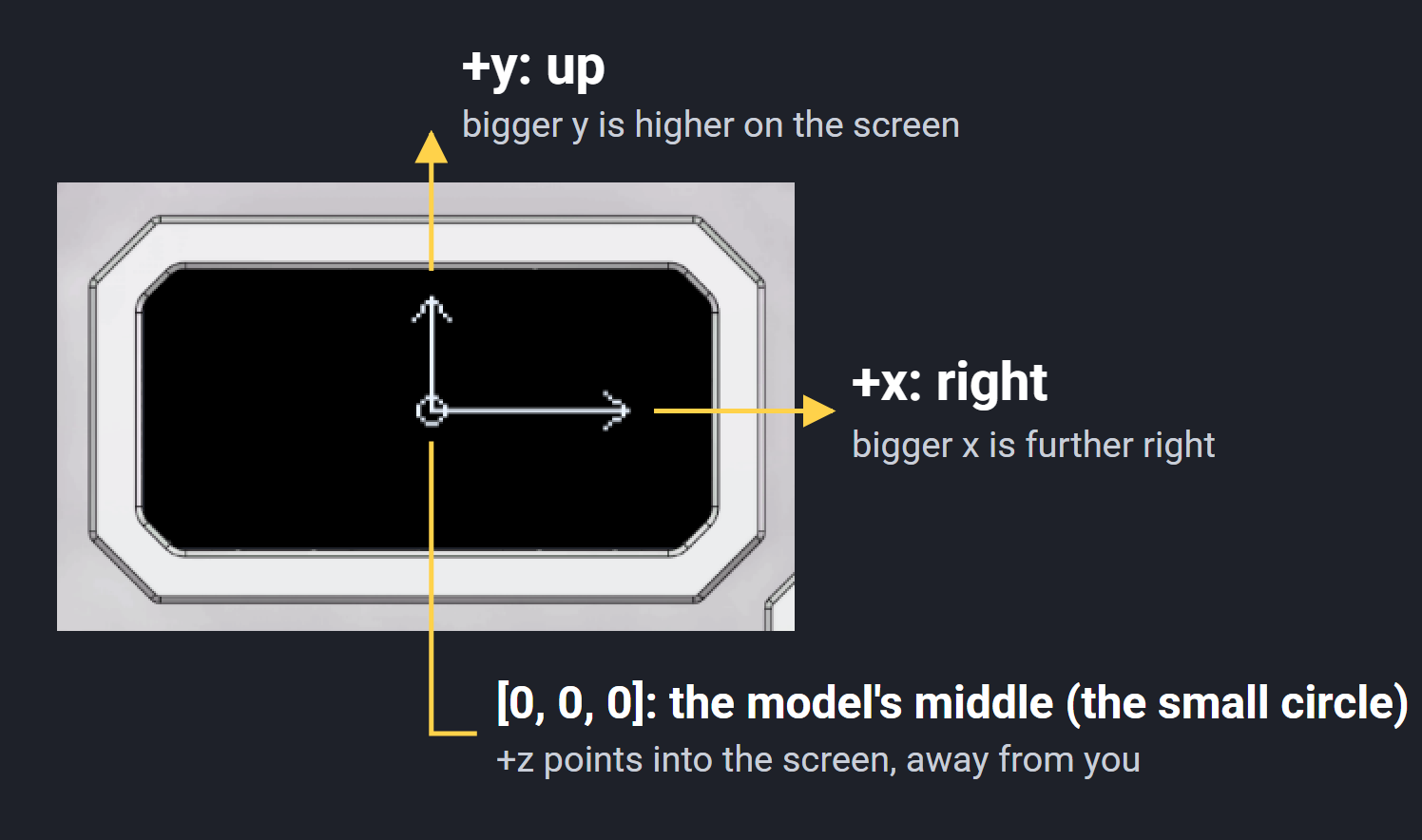
- x goes right, y goes up, and z goes into the screen, away from you. The point
[0, 0, 0]is the middle of the model. Put the model around the middle so it turns around its own middle. - Each number is a whole number in the range listed under Limits at a glance. Decimals are refused.
- The number of points a model can have is also listed there.
The picture shows the directions on the emulator's screen. A small app draws two arrows as a model that is not turned, with its middle at the centre of the screen: the arrow along x points right and the arrow along y points up. Screen pixels count downward from the top, so a point with a bigger y is drawn higher on the screen, not lower. The app has perspective off, so z doesn't change where a point of an unturned model lands. With perspective on, a point with a bigger z is drawn closer to the model's middle, because it is further away.
 - The first point in the list is number 0, the second is number 1, and so on. Edges refer to points by these numbers, so reordering the list changes the model unless you update the edges.
Edges
edges is a list of lines. Each line is a list of exactly two point numbers, [a, b], which join point a to point b. The order of the two numbers does not matter.
- Each number must be a whole number from 0 up to one less than the number of points.
- A line from a point to itself, such as
[3, 3], is refused. - The number of lines a model can have is listed under Limits at a glance.
Two things are allowed but flagged as warnings, because they are probably mistakes:
- A line that repeats another line (
[0, 1]and[1, 0]are the same line). - A point that no line touches.
Worked example: the ship
The Spaceship app in the firmware draws its ship from this file.
{
  "schemaVersion": 1,
  "meta": {
    "name": "ship",
    "kind": "mesh",
    "author": "Dismo Industries",
    "license": "GPL-3.0-or-later",
    "symmetry": "x"
  },
  "vertices": [
    [0, 12, 0],
    [0, -8, 2],
    [-3, -6, -2],
    [3, -6, -2],
    [-2, 1, 0],
    [2, 1, 0],
    [-17, -5, -1],
    [17, -5, -1],
    [-17, 2, 5],
    [17, 2, 5],
    [0, 4, 4],
    [-2, 2, 2],
    [2, 2, 2],
    [-5, -7, -1],
    [5, -7, -1]
  ],
  "edges": [
    [0, 2], [0, 3], [2, 1], [3, 1], [0, 1],
    [4, 6], [6, 2], [5, 7], [7, 3],
    [6, 8], [7, 9],
    [10, 11], [10, 12], [11, 12], [10, 0],
    [2, 13], [3, 14], [13, 14]
  ]
}
(The file in the firmware lists each point and line on its own row. The meaning is the same.)
What each part does:
| Part | What it is |
|---|---|
schemaVersion: 1 |
The only version of the format. |
meta.name |
"ship", so the app's code refers to the model as cf::gfx::ship::ship. |
meta.author, meta.license |
Who made the model and the license it is shared under. |
meta.symmetry |
"x": the ship is the same on both sides. Points 2 and 3, 4 and 5, 6 and 7, 8 and 9, 11 and 12, and 13 and 14 are left and right twins: their x numbers are opposites (-3 and 3) and their y and z numbers match. Points 0, 1 and 10 sit on the middle line, with an x of 0. |
Point 0, [0, 12, 0] |
The highest point: 12 units up from the middle. This is the nose. |
Point 1, [0, -8, 2] |
The lowest point on the middle line: 8 units down. |
Points 6 and 7, [-17, -5, -1] and [17, -5, -1] |
The two outermost points, 17 units to the left and to the right. They make the ship its widest. |
Point 10, [0, 4, 4] |
A point on the middle line, 4 units up and 4 units along z. |
[0, 2], [0, 3], [2, 1], [3, 1], [0, 1] |
The body: lines from point 0 down both sides to point 1, and one line straight down the middle. |
[4, 6], [6, 2], [5, 7], [7, 3], [6, 8], [7, 9] |
The wings: on each side, a line from a point near the middle out to the outer point, a line from the outer point to the body, and a line from the outer point to a point 7 units higher and 6 units along z. |
[10, 11], [10, 12], [11, 12], [10, 0] |
A small triangle (points 10, 11 and 12) and a line from point 10 to the nose. |
[2, 13], [3, 14], [13, 14] |
Two lines from the body's lower points (2 and 3) to a pair of points just outside and below them (13 and 14), and a line across between those two. |
This ship has 15 points and 18 lines, well inside the limits.
How a file becomes code
When you build an app, the Studio turns each model file into a block of code: a list of points, a list of lines, and a Mesh that holds both. It refuses a file that breaks any rule above.
The model's meta.name is changed into a code name:
- Capital letters become lower case.
- Accents are dropped.
- Each run of spaces or symbols becomes one
_. - A name that would start with a digit gets a
_in front. A name left empty by these steps becomesmodel.
So "Arrow" becomes cf::gfx::arrow::arrow, which is the line the 3D tab shows under Use in code. The original name stays inside the Mesh as its text label. See 3D Models for how to use the mesh in an app.
The Studio draws the model in its preview with the same whole-number math as the Fidget, so the preview matches the screen. Each point goes through a projection: the step that works out where a 3D point lands on the flat screen. The math is described under The drawing math.
Limits at a glance
| Limit | Value |
|---|---|
| Format version | 1 |
| Points | 0 to 96 |
| Lines | 0 to 160 |
| Each coordinate | whole number, -128 to 127 |
| Each line | exactly two point numbers, different from each other |
| Top-level fields | exactly schemaVersion, meta, vertices, edges |
The 3D Models page lists the limits for meshes written directly in code, which are higher.
Where to go next
- 3D Models: use a model in an app.
- 3D Models in the Studio: draw, import and save models.
- Import & export: moving model files in and out of a project.